
When measuring voltage, you’re checking the electrical potential difference between two points to see how much energy is available to push electrons through a circuit. Current measurement tells you how much charge flows through a wire at a given time, while resistance shows how much a component opposes that flow. Each one requires different techniques and safety precautions. Understanding these differences helps you troubleshoot effectively and avoid mistakes—keep exploring to get a clearer picture of how they all work together.
Key Takeaways
- Voltage measures electrical potential difference between two points, indicating energy available to move electrons.
- Current measures the flow rate of electrons through a circuit, reflecting the amount of charge passing per unit time.
- Resistance quantifies how much a component or material opposes the flow of current within a circuit.
- Different measurement techniques and equipment are required for voltage, current, and resistance to ensure accuracy and safety.
- Proper understanding of each quantity helps diagnose circuit issues and prevents damage or safety hazards.
Understanding the differences between measuring voltage, current, and resistance is crucial when working with electrical circuits. Each measurement provides unique information that helps you analyze and troubleshoot circuits effectively, but it’s equally important to prioritize electrical safety. When you’re conducting circuit analysis, knowing what each quantity represents guarantees you don’t make dangerous assumptions that could lead to accidents or equipment damage.
Voltage, or electrical potential difference, tells you how much energy is available to push electrons through a circuit. When you measure voltage, you’re fundamentally checking the electrical pressure between two points. This is useful when diagnosing issues like voltage drops or confirming power supply levels. It’s important to remember that voltage measurements are typically taken with the circuit powered on, so you should use proper equipment and techniques to avoid electrical shock. Always ensure your multimeter is set correctly and insulated probes are used to prevent accidental contact with live parts, reinforcing electrical safety. Being aware of measurement safety protocols is essential to prevent accidents during testing. Additionally, understanding how different measurement techniques impact circuit behavior is key to accurate diagnostics and safety. Recognizing the effects of measurement methods can help prevent unintended circuit disruptions or damage. A clear comprehension of electrical quantities helps prevent misinterpretation of your measurements, which can otherwise lead to incorrect troubleshooting steps. Moreover, understanding the role of insulation and protective gear during measurements further enhances safety and accuracy.
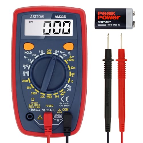
AstroAI Digital Multimeter Tester 2000 Counts with DC AC Voltmeter and Ohm Volt Amp Meter; Measures Voltage, Current, Resistance, Continuity and Diode, Blue
- Measurement Capabilities: Voltage, Current, Resistance, Diode, Continuity
- Versatile Use: Ideal for household and automotive testing
- Display Features: Backlight LCD with 3 ½ digits
As an affiliate, we earn on qualifying purchases.
As an affiliate, we earn on qualifying purchases.
Frequently Asked Questions
How Do Temperature Variations Affect Measurements?
Temperature effects can considerably impact your measurements, making them less accurate. As temperature rises, components like resistors and conductors change their properties, often increasing resistance or altering voltage readings. Conversely, colder temperatures can decrease resistance and affect current flow. To guarantee measurement accuracy, you should control or account for temperature variations, use temperature-compensated instruments, and perform calibration under consistent conditions. This helps you get reliable, precise results every time.
What Safety Precautions Should Be Taken When Measuring Electrical Parameters?
Did you know that electrical accidents cause over 1,000 deaths annually worldwide? When measuring electrical parameters, always wear proper safety gear like insulated gloves and goggles to protect yourself. Make certain all equipment has proper insulation and is rated for the voltage you’re testing. Turn off power before connecting or disconnecting devices, and use insulated tools. These precautions help prevent shocks, burns, and other hazards, keeping you safe during measurements.
Can Digital Multimeters Measure All Three Parameters Simultaneously?
Digital multimeters typically can’t measure voltage, current, and resistance simultaneously because they require different settings and connections. To guarantee accurate readings, you should follow proper calibration procedures and verify instrument compatibility for each parameter. When measuring multiple parameters, switch the multimeter’s functions accordingly, and be cautious with connections to avoid damage or inaccurate data. This approach helps you get precise readings efficiently and safely.
How Does Lead Placement Influence Measurement Accuracy?
Lead placement profoundly influences measurement accuracy because proper placement guarantees accurate readings. Incorrect lead positioning can introduce errors, affecting your results. To maintain lead placement accuracy, always double-check connections before measuring. Additionally, perform measurement calibration regularly, especially if you notice inconsistent readings. Proper lead placement combined with regular calibration helps you obtain precise voltage, current, and resistance measurements, ensuring confidence in your multimeter’s results.
What Are Common Mistakes to Avoid During Measurements?
Did you know that calibration errors are responsible for nearly 20% of inaccurate measurements? To avoid common mistakes, always double-check your instrument selection to guarantee it’s suitable for your measurement type. Never skip calibration, as it can lead to significant errors. Also, avoid touching test leads during measurement to prevent interference. These steps help you get accurate readings and prevent costly mistakes.
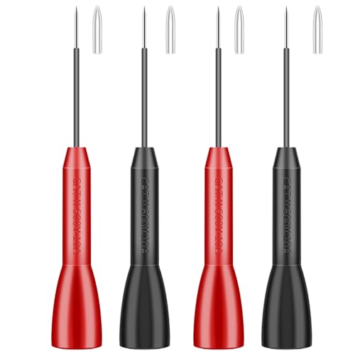
4 Pack 2mm Extended multimeter Needle Test Probes, 600V/10A Non-Destructive
- Compatibility: Fits Fluke and other multimeters
- Material Quality: Industrial-grade PVC and stainless steel
- Precision Needles: 0.2mm diameter for accuracy
As an affiliate, we earn on qualifying purchases.
As an affiliate, we earn on qualifying purchases.
Conclusion
Understanding the differences between measuring voltage, current, and resistance helps you see how they work together in circuits. Think of voltage as the pressure pushing electrons, current as the flow of those electrons, and resistance as the obstacle slowing them down. Visualize a water hose: voltage is the water pressure, current is the flow rate, and resistance is the narrow nozzle. Grasping these concepts makes troubleshooting and designing circuits much clearer and more effective.

Fluke 323 Clamp Meter for Commercial/Residential Electricians, Measures AC Current to 400 A & AC/DC Voltage to 600 V, Resistance and Continuity, Includes 2 Year Warranty and Soft Carrying Case
- AC Current Measurement: Measures up to 400 A AC
- Voltage Measurement: Measures AC/DC voltage up to 600 V
- Resistance & Continuity: Measures resistance to 4 kΩ with continuity detection
As an affiliate, we earn on qualifying purchases.
As an affiliate, we earn on qualifying purchases.

Portable Mini Inductor Tester, Type-C Powered High Precision Mainboard Coil Testing Tool, Fast Inductance Fault Detection Diagnosis Repair Tool for Mobile Phone Electronic Components-2 Pcs
- Instant In-Circuit Testing: Detects coil faults without desoldering
- Type-C Power Supply: Powered directly from Type-C devices
- Plug & Play Design: No drivers or calibration needed
As an affiliate, we earn on qualifying purchases.
As an affiliate, we earn on qualifying purchases.